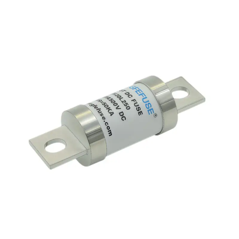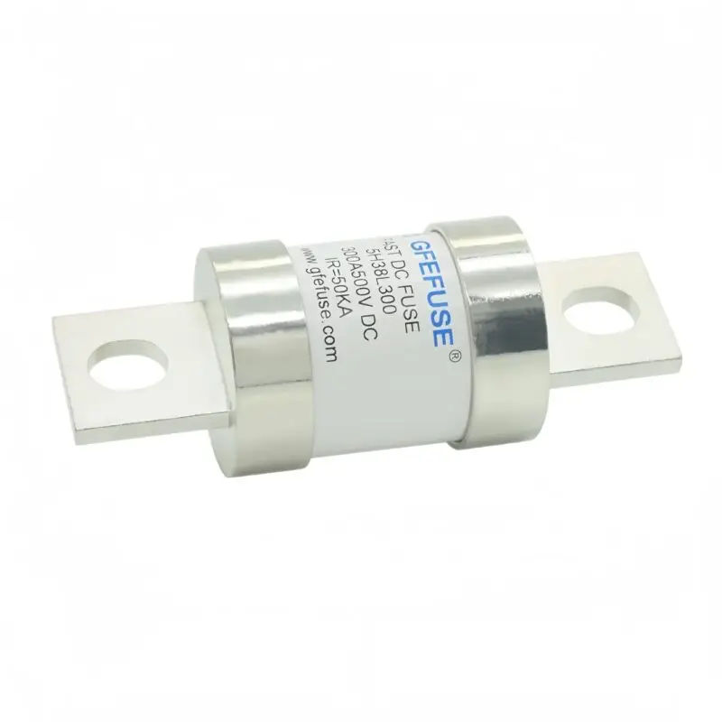










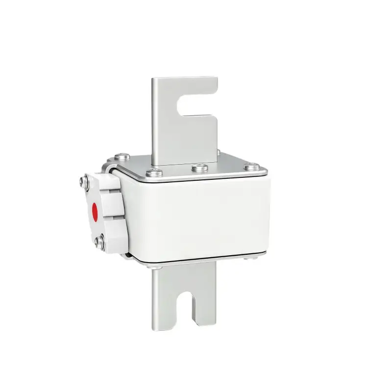
GFEVT500‑K‑51E Series Square‑Body Fast‑Acting DC Fuse Links (Size 1#,100‑800A,500Vdc)
GFEVT500‑K‑51E Size1# aR Fast‑Acting DC Fuse,100‑800A 500Vdc,50kA interrupting capacity.</strong> Optional with / without blow‑indicator, UL248‑13 & IEC60269‑4, RoHS REACH for energy‑storage battery pack protection. Request datasheet & quotation.
20+ Years Experience
Over 20 years in electrical protection and fuse manufacturing.
Strict Quality Control
Rigorous testing ensures reliable product performance.
Get a Quote
GFEVT500‑K‑51E Series Square‑Body Fast‑Acting DC Fuse Links (Size 1#,100‑800A,500Vdc)
Product Overview
The GFEVT500-K-51E Size1# is a DC fuse designed as an aR fast-acting square-body fuse for energy-storage battery pack protection. This fuse supports 500Vdc at 100-800A with 50kA interrupting capacity.
,GFEVT500‑K‑51E is GFEV Size1# square‑body aR‑class fast‑acting DC semiconductor fuse link, rated 500Vdc, 100A‑800A. Two mechanical configurations are available: K‑51E (standard): equipped with fuse blow indicator; KN‑51E (optional): without fuse blow indicator.
Optimized for heavy‑duty DC fault‑protection. Max interrupting capacity reaches 50kA@500Vdc, ultra‑short time constant ≤3 ms, minimum breaking current ≥3×In. Features excellent DC breaking performance, low watt loss, ≥20g high‑frequency vibration resistance, superior cycling capability. Complies with UL248‑1/248‑13, IEC60269‑1/60269‑4, RoHS; REACH declaration available on request. Widely used for battery‑pack, energy‑storage system and DC relay backup protection.
Note:Product specifications subject to change without prior notice.
Key Features & Benefits
‑ ✔ aR Fast‑Acting DC‑optimized Design: Time constant ≤3 ms, extremely fast opening upon high‑fault‑current events, reliably protect semiconductors & battery circuits.
‑ ✔ High Breaking Performance: 50 kA max interrupting capacity @500Vdc; minimum breaking current ≥3 In.
‑ ✔ Two Indicator Options: Standard K‑51E with blow indicator; optional KN‑51E without indicator for compact installation.
‑ ✔ Low Watt Loss: Reduce heat accumulation, improve whole‑system energy efficiency.
‑ ✔ Superior Mechanical Reliability: ≥20 g high‑frequency vibration resistance, excellent shock‑impact endurance for harsh new‑energy site conditions.
‑ ✔ Comprehensive Environmental Adaptability: Support derating calculation for ambient‑temperature, altitude and forced‑air‑cooling scenarios.
‑ ✔ Full‑standard Compliance: UL248‑13, IEC60269‑4; RoHS compliant; REACH document available upon request.
‑ ✔ Superior cycling capability, outstanding anti‑current‑impulse performance.
General Technical Specifications
| Item | Parameter |
|---|---|
| Series | GFEVT500‑K‑51E Series, Size 1# |
| Rated Voltage | 500 Vdc |
| Rated Current Range | 100A ~ 800A |
| Utilization Class | aR (semiconductor protection) |
| Max Interrupting Capacity | 50 kA @500 Vdc |
| Minimum Breaking Current | ≥3 In |
| Time Constant | ≤3 ms |
| Versions | K‑51E (with indicator‑standard); KN‑51E (without indicator‑optional) |
| Vibration Resistance | ≥20 g high‑frequency vibration |
| Normal Operating Ambient Temp | ‑5℃ ~ +40℃ |
| Allowable Operating Ambient Temp | ‑40℃ ~ +85℃ |
| Storage Temperature | ‑40℃ ~ +120℃ |
| Standards | UL248‑1 / UL248‑13; IEC60269‑1 / IEC60269‑4; RoHS, REACH available |
| Recommended Continuous Working Current | ≤75 % of fuse rated In |
Model List & Electrical Ratings (50kA@500Vdc)
Replace suffix XX with K‑51E(with indicator) or KN‑51E(without indicator).
| Part Number | Rated Current(A) | Size | Melting A²s | Clearing A²t | Power Loss(W,100%) |
|---|---|---|---|---|---|
| GFEVT500‑100XX‑51E | 100 | 1# | 820 | 7370 | 23 |
| GFEVT500‑125XX‑51E | 125 | 1# | 1340 | 11910 | 28 |
| GFEVT500‑160XX‑51E | 160 | 1# | 2410 | 21550 | 35 |
| GFEVT500‑200XX‑51E | 200 | 1# | 3030 | 26910 | 38 |
| GFEVT500‑250XX‑51E | 250 | 1# | 5050 | 45680 | 52 |
| GFEVT500‑275XX‑51E | 275 | 1# | 6140 | 59220 | 55 |
| GFEVT500‑315XX‑51E | 315 | 1# | 7910 | 75060 | 64 |
| GFEVT500‑350XX‑51E | 350 | 1# | 10520 | 100260 | 68 |
| GFEVT500‑400XX‑51E | 400 | 1# | 15060 | 143820 | 72 |
| GFEVT500‑450XX‑51E | 450 | 1# | 20830 | 205160 | 78 |
| GFEVT500‑500XX‑51E | 500 | 1# | 26760 | 264150 | 87 |
| GFEVT500‑550XX‑51E | 550 | 1# | 36520 | 363150 | 92 |
| GFEVT500‑630XX‑51E | 630 | 1# | 53800 | 554220 | 100 |
| GFEVT500‑700XX‑51E | 700 | 1# | 71550 | 742770 | 102 |
| GFEVT500‑800XX‑51E | 800 | 1# | 99540 | 1035000 | 113 |
Dimension Drawings & Two Versions
Insert engineering drawing images here:
‑ H3:K‑51E:Standard version drawing with fuse blow indicator
‑ H3:KN‑51E:Optional version drawing without indicator
Important Reminder:
- Refer to original datasheet for full dimension tolerances for mechanical design.
- For high‑altitude, high‑ambient‑temp closed‑cabinet installation, rated‑current derating calculation is mandatory.
Time‑Current & Derating Curves Reference
Insert three charts:
- Time‑Current characteristic curve (accuracy ±15 % current error; minimum breaking current=3 In)
- Ambient‑temperature derating coefficient curve
- Altitude rated‑current correction coefficient curve
Key application notes: ‑ For ambient temperature >40 ℃, apply temperature‑derating factor Kt to reduce allowable continuous current. ‑ For altitude 2000‑4500 m closed‑environment cabinet: derate 2‑5 % rated‑current per 1000 m elevation increase. ‑ Forced air cooling can improve continuous‑current capacity, refer Kv wind‑speed correction curve.
Typical Application Fields
‑ Battery Energy‑Storage System (BESS), battery pack main‑circuit over‑current protection ‑ BMS & DC relay backup protection ‑ Renewable‑energy energy‑storage power conversion equipment ‑ Industrial heavy‑current DC power supply & rectifier units ‑ Stationary energy‑storage cabinet & energy‑storage container ‑ Heavy‑duty DC equipment with high short‑circuit‑fault‑risk
Standards & Compliance
‑ Reference Standard: UL 248‑1, UL 248‑13; IEC 60269‑1, IEC 60269‑4 ‑ Environmental: RoHS Compliant; REACH declaration available upon request ‑ Mechanical: High vibration & shock resistance ≥20 g
Packing & Sample Inquiry
‑ Standard packing: Factory bulk carton packing. ‑ Engineering samples available for performance‑verification testing. ‑ MOQ negotiable for project orders. ‑ Send inquiry to obtain full datasheet, 2D drawing, I²t data sheet and quotation.
Frequently Asked Questions
1: What is difference between K‑51E and KN‑51E suffix?
1: K‑51E (standard): built‑in fuse blow indicator; KN‑51E (optional): no fuse‑blow indicator for compact space‑saving installation.
2: What is time‑constant for GFEVT500‑K‑51E fuse?
2: Time constant ≤3 ms, ultra‑fast clearing for DC short‑circuit faults; minimum breaking current ≥3×In.
3: What derating factors should engineers consider for this fuse?
3: Three critical factors: ambient‑temperature(Kt), installation altitude(Ka), forced‑air‑cooling(Kv). In closed cabinet above 40 ℃ or altitude >2000 m, rated‑current must be properly derated. Recommended continuous operating current ≤75 % nominal In under standard‑condition.
4: What certification documents can you provide?
4: RoHS compliant; REACH declaration document can be provided on customer request; comply with UL248‑13 & IEC60269‑4 standards.
5: What is max interrupting rating?
5: Max interrupting capacity is 50 kA @500 Vdc, minimum breaking current ≥3×In.
Bottom CTA block Need datasheet, drawing, sample or quotation for GFEVT500‑K‑51E series square‑body dc fuse? Submit inquiry form, our technical‑sales team will reply you within 24 working hours.
GFEVT500‑K‑51E Size1# square‑body fast‑acting dc fuse EssFuse