









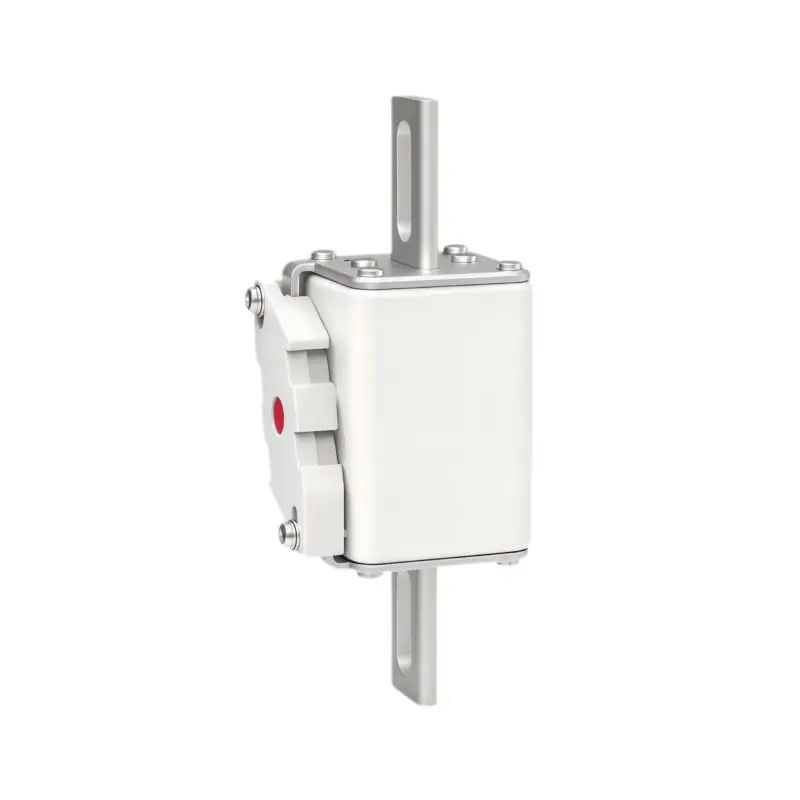
GFEVT1000‑B‑43E‑Series 1000Vdc Fast‑Acting Square‑Body DC Fuse (50A‑400A, Size01*, aR Class)
GFEVT1000‑B‑43E size01* blade‑terminal dc fuse,1000Vdc,50‑400A,50kA@1000Vdc(L/R≤2ms),with/without indicator for ESS & battery pack.UL248.13,IEC60269.4,RoHS.Request datasheet & quote.
20+ Years Experience
Over 20 years in electrical protection and fuse manufacturing.
Strict Quality Control
Rigorous testing ensures reliable product performance.
Get a Quote
GFEVT1000‑B‑43E‑Series 1000Vdc Fast‑Acting Square‑Body DC Fuse (50A‑400A, Size01*, aR Class)
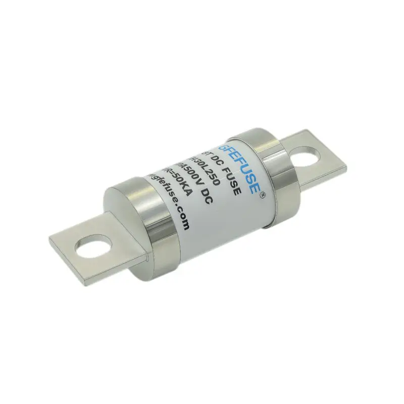
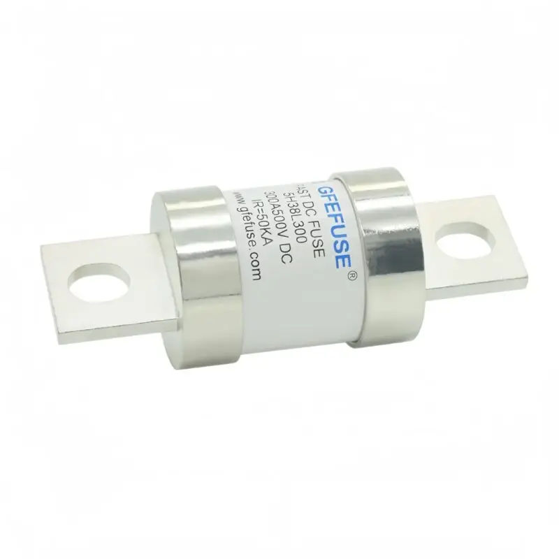
The GFEVT1000‑B‑43E‑Series is Size01* square‑body fast‑acting DC fuse with blade terminals manufactured by GFEFUSE. Specifically, it rates for 1000Vdc and covers current specifications ranging from 50A up to 400A. Compared with stud‑mount DC fuses, it delivers 50kA interrupting capacity with L/R ≤2 ms and minimum breaking current of 3In. Furthermore, two variants are available:‑B‑43E with built‑in blow‑out indicator and ‑BN‑43E without indicator. Therefore, flat‑blade terminals simplify bus‑bar installation for energy‑storage cabinets and lithium‑ion battery‑pack short‑circuit backup protection.
Product Overview
Core Design Purpose
Designed for heavy‑duty 1000Vdc direct‑current circuits, this Size01* square‑body fuse focuses on short‑circuit backup protection for new‑energy power equipment. Besides, its high‑voltage rating allows designers to select smaller, cost‑effective conductors to raise overall system efficiency. In addition, the flat blade terminals bring convenient assembly for bus‑bar cabinet layouts.
Fault‑Interrupt Performance
Under severe fault‑current conditions, this fuse can open up to ten times faster than conventional fuse links. As a result, it can effectively protect lithium‑ion batteries, power semiconductors and internal wiring against destructive short‑circuit damage. Moreover, it delivers great ampacity within fixed Size01* outer dimensions with low I²t characteristics.
Environmental & Mechanical Adaptability
This product carries strong resistance against current impulse and wide‑range ambient‑temperature tolerance. Notably, high‑frequency vibration resistance reaches ≥20g acceleration. For cabinet‑mount energy‑storage devices or battery systems, such mechanical performance brings stable long‑term operation. Meanwhile, the time‑current characteristic curve holds accuracy within ±15% current‑direction error.
Key Features & Benefits
Core Protection Advantages
In particular, this compact Size01* fuse suits small‑medium new‑energy cabinet projects. It includes these core advantages:
- ✅ Rated voltage 1000Vdc, compact Size01* square‑body mechanical structure
- ✅ Fast‑acting aR‑class protection; interrupt rating 50kA@1000Vdc (L/R ≤2 ms), minimum breaking‑current ≥3In
- ✅ Flat blade‑type terminals, convenient for bus‑bar direct mounting
- ✅ Dual‑version options: ‑B‑43E with blow‑out indicator; ‑BN‑43E without indicator, identical electrical performance
- ✅ Complete current portfolio: 50A‑400A full‑range stock specifications
- ✅ Low watt‑loss property reduces extra heat generation inside power cabinets
- ✅ Superior mechanical shock & vibration resistance ≥20g acceleration
- ✅ Optimized for battery‑pack, ESS, DC relay backup scenarios
- ✅ RoHS compliant; REACH documentation available upon buyer request
Main Electrical Ratings
Electrical Parameter Summary
In addition, all I²t test conditions run at 50kA @1000Vdc.
| Rated Voltage | 1000 Vdc |
| Rated Current Range | 50A‑400A (Size01*) |
| Operating Class | aR (semiconductor / battery backup protection) |
| Rated Breaking Capacity | 50 kA @1000Vdc, L/R ≤2 ms |
| Minimum Breaking Current | ≥3.0 × In |
| Test I²t Condition | 50 kA @1000Vdc |
| Time‑Current Curve Tolerance | ±15% current‑direction error |
| Recommended Continuous Operating Current | ≤75% of nominal fuse rating |
| Terminal Type | Flat blade‑type for bus‑bar connection |
Complete Part‑Number Ratings Table
Model & Performance Data Sheet
Important note:‑BN‑43E series inherit exactly same electrical data, only remove blow‑out indicator.
| Part No. | Fuse Amps | Breaking Capacity | A²s Melting @50kA/1000Vdc | A²t Clearing @50kA/1000Vdc | 100% Power Loss(W) | Variant |
|---|---|---|---|---|---|---|
| GFEVT1000‑50B‑43E | 50A | 50kA | 137 | 1,000 | 16 | With indicator |
| GFEVT1000‑63B‑43E | 63A | 50kA | 215 | 1,620 | 19 | With indicator |
| GFEVT1000‑80B‑43E | 80A | 50kA | 410 | 3,145 | 23 | With indicator |
| GFEVT1000‑100B‑43E | 100A | 50kA | 740 | 5,645 | 29 | With indicator |
| GFEVT1000‑125B‑43E | 125A | 50kA | 1,460 | 10,860 | 34 | With indicator |
| GFEVT1000‑160B‑43E | 160A | 50kA | 2,535 | 19,850 | 41 | With indicator |
| GFEVT1000‑200B‑43E | 200A | 50kA | 5,070 | 38,200 | 46 | With indicator |
| GFEVT1000‑250B‑43E | 250A | 50kA | 8,970 | 68,550 | 51 | With indicator |
| GFEVT1000‑315B‑43E | 315A | 50kA | 18,200 | 142,950 | 61 | With indicator |
| GFEVT1000‑350B‑43E | 350A | 50kA | 26,400 | 199,500 | 66 | With indicator |
| GFEVT1000‑400B‑43E | 400A | 50kA | 38,750 | 293,500 | 74 | With indicator |
Mechanical Dimensions(Size01*, Blade‑type Terminal, B‑43E / BN‑43E)
Outline & Terminal Specification
Meanwhile, overall body dimension: 138.5±2.5 mm total length, body width & height: 43±2 mm ×58±3 mm. Terminal type: flat blade‑type terminals for bus‑bar mounting. ‑B‑43E equips blow‑out visual alarm;‑BN‑43E omits indicator unit.
Insert WebP‑format dimension drawing for B‑43E and BN‑43E.
Application Fields
Target Market & Use Cases
For instance, many compact energy‑storage cabinet engineers select this blade‑terminal series to simplify bus‑bar wiring work. Main application scenarios:
- Typical New‑Energy Scenarios: Lithium‑ion Battery Pack over‑current & short‑circuit protection
- Energy‑Storage System(ESS / BESS)DC‑side backup protection
- Backup protection for DC relay & DC contactor
- Industrial DC Equipment: DC power cabinet with bus‑bar layout & industrial DC converter protection
Standards & Approvals
Compliance Certifications
Moreover, this fuse references international industry specifications: UL 248.1, UL 248.13; IEC 60269‑1, IEC 60269‑4. All current ratings are RoHS compliant. REACH document release available upon formal customer request. As a result, time‑current characteristic accuracy keeps ±15% current‑direction error.
Operating Conditions & Derating Rules
Storage Environment
Product storage temperature: ‑40℃~+120℃; package storage temperature:‑40℃~+80℃. Humidity limits: RH≤70%@40℃, RH≤80%@30℃, RH≤90%@20℃.
Temperature Derating Guidance
Standard operating temperature ranges from ‑5℃ ~+40℃. Allowable working temperature covers ‑40℃ ~+85℃. However, users must apply temperature‑derating factor Kt when ambient temperature rises above 40℃. Below ‑5℃, low‑overload pre‑arcing time will extend slightly.
Altitude Derating Guidance
Normal installation altitude shall not exceed 2000 m. For closed‑box cabinets operating above 2000 m while internal temperature stays above 40℃, derate rated‑current 2%‑5% per 1000 m. As altitude rises between 2000‑4500 m, air insulation strength reduces 12‑15% per 1000 m. Therefore, follow GB/T16935.1 to adjust insulation clearance. Correction formula: Ka = 1‑(H‑2000)/100*(0.5/100).
Continuous‑Current Restriction
As an important installation note: long‑term operating current must stay ≤75% × nominal In.
Insert three charts: temperature‑derating Kt curve, altitude‑derating Ka curve, forced‑air‑cooling Kv curve.
Installation & Conductor Sizing Requirement
Blade‑Terminal Fastening
Use proper bolts to fasten blade terminals against bus‑bar. You need to guarantee stable low contact resistance during assembly.
Cable / Bus‑Bar Selection
Besides, select copper conductor or bus‑bar cross‑section strictly according to conductor‑sizing reference table inside datasheet.
Mounting Orientation
Horizontal, vertical and tilted installation are all supported. Nevertheless, avoid negative gravity‑vibration impact for connection structures.
Safety Reminders
Do NOT replace fuse under load, unless the system equips dedicated fuse‑disconnector switch. Reserve sufficient insulation clearance between live‑parts and ground. In particular, high‑altitude sites need extra insulation safety margin. Any mechanically‑damaged fuse requires immediate replacement. During regular equipment maintenance, clean dust and oxide layers on conductive contact surfaces.
Frequently Asked Questions
1: What is breaking‑capacity & time‑constant of GFEVT1000‑B‑43E series?
A: Rated breaking‑capacity 50kA @1000Vdc, time‑constant L/R ≤2 ms; minimum breaking‑current ≥3 times nominal rated current (3In).
2: What is the difference between suffix ‑B‑43E and ‑BN‑43E?
A: ‑B‑43E: with built‑in blow‑out visual indicator; ‑BN‑43E: no indicator. Both share same electrical parameters and blade‑terminal mechanical dimensions.
3: What terminal type does this fuse adopt?
A: Flat blade‑type terminals for direct bus‑bar connection.
4: What is recommended long‑term continuous operating current?
A: Continuous working current shall not exceed 75% of fuse nominal ampere rating.
5: Which standards does GFEVT1000‑B‑43E comply with?
A: Reference UL248.1 / UL248.13, IEC60269‑1 / IEC60269‑4. RoHS compliant; we provide REACH declaration upon customer request.
6: Is derating required for closed‑cabinet high‑altitude deployment?
A: Yes. For closed cabinets with internal temperature >40℃ above 2000 m altitude, derate rated‑current 2%‑5% per 1000 m elevation. However, open‑air installation generally ignores altitude‑related derating.
Download Datasheet & Get Quotation
👉 Download Datasheet & Get Quotation|Request Technical Support & Bulk Quotation
Form fields suggestion: Required rated current, Variant choice(B‑43E with indicator / BN‑43E no indicator), System DC voltage, Cabinet ambient temperature, Working altitude, Application scenario, Order quantity.