










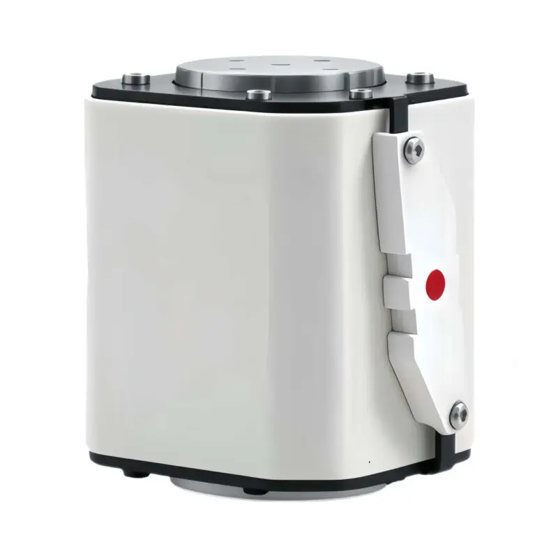
GFHVT1500‑S‑105E 1500Vdc Fast‑Acting Fuse 400‑2000A
GFHVT1500‑S‑105E bolt‑on DC fuse,1500Vdc,400‑2000A,aR 250kA@L/R≤5ms. For BESS,wind‑power & DC‑drive. Download datasheet.
20+ Years Experience
Over 20 years in electrical protection and fuse manufacturing.
Strict Quality Control
Rigorous testing ensures reliable product performance.
Get a Quote
GFHVT1500‑S‑105E Series 1500Vdc Fast‑Acting Bolt‑Connected Square‑Body Fuse 400‑2000A
Product Overview
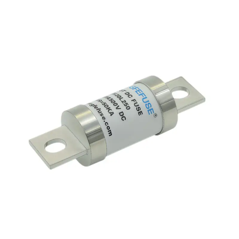
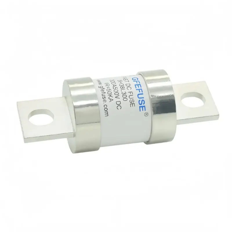
The GFHVT1500-S-105E is a DC fuse designed as a bolt-on fast-acting fuse for BESS and wind-power DC drive systems. This fuse supports 1500Vdc at 400-2000A with aR 250kA breaking capacity at L/R≤5ms.
,The GFHVT1500‑S‑105E series is heavy‑duty square‑body fast‑acting aR fuse link with S‑type two‑M12 bolt‑on busbar terminals, purpose‑built for high‑power DC circuits with low L/R time‑constant. Rated for 1500Vdc, current range 400A‑2000A, maximum interrupting capacity 250kA@1500Vdc (L/R ≤5ms), minimum breaking current>3In.
This high‑current bolt‑mount fuse features low arc‑voltage and low let‑through I²t, excellent charge‑discharge cycling performance and ≥20g shock‑vibration resistance. Tin‑plated (3‑5μm) terminal surface ensures stable bus‑bar contact. Optimized for megawatt‑scale energy‑storage, wind‑power converter and heavy‑duty DC‑drive equipment.
Key Features & Benefits
- ✅ S‑type 2‑pcs M12 bolt‑on busbar connection, compact heavy‑duty for high‑current power loop
- ✅ Rated voltage 1500V DC, suitable for large‑scale DC energy‑storage architecture
- ✅ Fast‑acting aR semiconductor‑protection characteristic; low arc‑voltage & low let‑through I²t
- ✅ Interrupt rating: 250 kA @1500Vdc (L/R ≤5ms), minimum breaking current>3In
- ✅ Superior charge‑discharge cycling capability for frequent fluctuating DC working conditions
- ✅ Excellent mechanical shock & vibration resistance (≥20g), fits wind‑turbine & container‑ESS cabinet
- ✅ 3‑5μm tin‑plated contact surface for anti‑oxidation and stable electrical connection
- ✅ RoHS compliant, REACH statement available upon request
- ✅ Designed per UL 248‑13, IEC 60269‑4 standards
Main Electrical Specifications
| Parameter | Specification |
|---|---|
| Rated Voltage | 1500 Vdc |
| Rated Current Range | 400A‑2000A |
| Fuse Class | aR Fast‑acting |
| Max Interrupt Capacity | 250 kA @1500Vdc (L/R ≤5ms) |
| Minimum Breaking Current | >3×In |
| Terminal Type | S‑type bolt‑on, 2 pcs M12 mounting holes |
| Screw hole spec | Max hole depth12.5mm; Min thread length12mm |
| Plating | Tin(Sn) plate,3‑5 microns |
| Storage Temperature | -40 ℃ ~ +120 ℃ |
| Normal Operating Ambient | -5 ℃ ~ +40 ℃ |
| Allowable Operating Temperature | -40 ℃ ~ +85 ℃ |
Note: Recommended continuous operating current ≤75 % of fuse nominal rating under standard ambient‑temperature conditions. DC interrupt performance strongly depends on circuit L/R time‑constant.
Part Numbering Explanation
Example Model: GFHVT1500‑1000S‑105E
| Code | Definition |
|---|---|
| GF | Manufacturer Code (GFEV) |
| HV | High‑Speed / Fast‑Acting |
| T | Ceramics Body |
| 1500 | Rated Voltage:1500Vdc |
| 1000 | Rated Current(A) |
| S | Terminal: S‑type bolt‑on connection |
| 105E | Series Code |
Mechanical Dimensions & Installation
S‑type two‑M12 bolt‑on terminals, compact heavy‑duty for high‑current bus‑bar assembly, tin‑plated contact surface. Dimensions: Length 153±3 mm; Install length137±2 mm; Height105±1.5 mm
Installation note: M12 screw hole; max hole depth12.5 mm, minimum thread length12 mm. Apply proper tightening torque to avoid over‑heating contact points. Tin plating thickness:3‑5 microns.
Full Part List Table
| Part Number | Fuse Amps | Melting A²s | Clearing A²s | Power Loss 1.0In(W) | RoHS |
|---|---|---|---|---|---|
| GFHVT1500‑400S‑105E | 400A | 25834 | 136415 | 190 | ● |
| GFHVT1500‑500S‑105E | 500A | 57389 | 276828 | 195 | ● |
| GFHVT1500‑630S‑105E | 630A | 117654 | 567527 | 228 | ● |
| GFHVT1500‑700S‑105E | 700A | 162326 | 783014 | 245 | ● |
| GFHVT1500‑800S‑105E | 800A | 240110 | 1158220 | 255 | ● |
| GFHVT1500‑900S‑105E | 900A | 345759 | 1667836 | 276 | ● |
| GFHVT1500‑1000S‑105E | 1000A | 470616 | 2270110 | 290 | ● |
| GFHVT1500‑1100S‑105E | 1100A | 623250 | 3006366 | 310 | ● |
| GFHVT1500‑1200S‑105E | 1200A | 754483 | 3620561 | 319 | ● |
| GFHVT1500‑1250S‑105E | 1250A | 918230 | 4429260 | 326 | ● |
| GFHVT1500‑1300S‑105E | 1300A | 1009830 | 5254527 | 335 | ● |
| GFHVT1500‑1350S‑105E | 1350A | 1294848 | 6245949 | 347 | ● |
| GFHVT1500‑1400S‑105E | 1400A | 1399970 | 6986564 | 352 | ● |
| GFHVT1500‑1500S‑105E | 1500A | 1581795 | 7630093 | 360 | ● |
| GFHVT1500‑1600S‑105E | 1600A | 1927554 | 9297929 | 372 | ● |
| GFHVT1500‑1800S‑105E | 1800A | 2734600 | 13190870 | 392 | ● |
| GFHVT1500‑2000S‑105E | 2000A | 3603985 | 18860380 | 410 | ● |
Application Fields
- ⚡ Large‑scale & container‑type Battery‑Energy‑Storage System(BESS) main‑circuit short‑circuit protection
- ⚡ Wind‑power converter / wind turbine DC‑link short‑circuit protection (low L/R circuit)
- ⚡ Heavy‑duty DC drives & industrial DC power equipment
- ⚡ Large‑capacity lithium‑ion battery‑cluster protection
- ⚡ DC bus‑bar over‑current & short‑circuit protection for high‑power energy‑storage station
Standards & Certifications
| Standard / Certificate | Status |
|---|---|
| UL 248‑13 | Design‑referenced |
| IEC 60269‑4 | Design‑referenced |
| RoHS | Compliant |
| REACH | Declaration available upon request |
Important: DC interrupt performance subject to actual circuit L/R time‑constant, confirm L/R ratio before project adoption. This variant is optimized for circuit L/R ≤5ms scenarios.
Operating & Derating Conditions
Important: Recommended continuous operating current ≤75 % of fuse nominal rating under standard conditions.
Ambient Temperature Derating
Above 40 ℃ ambient temperature requires rated‑current derating according to derating curve. Below ‑5 ℃, pre‑arcing time for low overload will slightly extend.
Altitude Derating
Normal working altitude ≤2000 m. For closed‑enclosure applications at altitude 2000‑4500 m: derate rated current 2‑5 % per 1000 m elevation increase. Air insulation strength drops at high altitude, check clearance per GB/T 16935.1.
Forced Air Cooling Correction
Forced ventilation improves heat‑dissipation and raises allowable continuous operating current, refer to Kv correction curve vs wind‑speed(m/s).
Time‑Current Characteristic Curves
- Curve‑1 covers rating 400‑1200A
- Curve‑2 covers rating 1250‑2000A
- Curve tolerance: ±15 % on current axis. Minimum breaking current>3 × In.
Frequently Asked Questions
1: What is the interrupt rating and minimum breaking current for GFHVT1500‑S‑105E?
1: 250kA@1500Vdc for L/R ≤5ms; minimum breaking current>3In. DC interrupt performance is highly dependent on circuit L/R time‑constant.
2: What does S‑type terminal mean?
2: S‑type is two‑M12 bolt‑on bus‑bar compact connection for high‑current heavy‑duty application, 3‑5μm tin‑plated contact surface for anti‑oxidation.
3: What is the difference between S‑105E and D‑105E?
3: S‑105E uses 2×M12 mounting holes (compact footprint); D‑105E uses 4×M10 mounting holes. Both share 250kA@L/R≤5ms interrupt rating, different mechanical installation footprint.
4: Can GFHVT1500‑S‑105E be used for wind‑turbine DC‑link protection?
4: Yes. Optimized for low L/R DC‑link in wind‑power converter, large‑scale BESS and heavy‑duty DC‑drive. Need I²t coordination and L/R validation.
5: What derating shall I apply for sealed cabinet working at high altitude?
5: For sealed cabinets operating above 2000 m altitude, derate 2‑5 % per 1000 m elevation. Higher derating ratio applies for larger‑ampacity models.
6: What is suggested maximum continuous operating current?
6: Under standard ambient‑temperature conditions, continuous working current should not exceed 75 % of fuse nominal rated‑current.
Download Datasheet & Resources
📄 Download GFHVT1500‑S‑105E Series Datasheet(PDF) GFHVT1500-S-105E-Series.-400-2000A-1500Vdc-IR-250kA-4-Fast-Acting fuse
📎 Request REACH Declaration | Request CAD Drawing | Ask Technical Support
Need fuse‑selection support? Contact our engineering team for I²t‑matching, L/R‑ratio evaluation and system‑coordination advice for your large‑power energy‑storage or wind‑power project.