नेविगेशन पर जाएं
मुख्य सामग्री पर जाएं अमूर्त
Stationary battery energy‑storage systems (BESS / ESS) present unique DC fault‑protection challenges that differ substantially from AC power‑system and photovoltaic applications. The absence of natural current zero‑crossing in DC circuits makes fault‑arc extinction more demanding for fuse‑links. In addition, battery‑source fault currents are influenced by battery chemistry, state‑of‑charge (SoC), internal impedance and circuit inductance‑resistance (L/R) time constant.
Improper fuse selection or poor protection coordination may result in nuisance opening, semiconductor device destruction, or even battery thermal‑runaway hazards. This article summarizes fuse classification, key application parameters, protection‑coordination principles and applicable international standards for stationary energy‑storage installations, intended for protection engineers and system integrators.
1. Core Difference: DC Fuse versus AC‑Rated Fuse
AC fuses take advantage of the inherent AC current zero point to extinguish electric arcs during fault interruption. In DC battery circuits, there is no natural current zero. The fuse must create an artificial current zero by arc‑voltage build‑up across the melting fuse‑link.
Important note: An AC‑rated fuse is not suitable for direct application within high‑voltage DC battery loops, even if its nominal AC voltage appears numerically higher than the DC operating voltage. The published breaking‑capacity of AC fuses is only validated under AC test conditions and cannot be extrapolated to DC fault scenarios.
2. Key Application Parameters for ESS DC Fuse‑Links
2.1 Rated DC Voltage (Uₙ DC)
The fuse’s rated DC operating voltage must exceed the maximum open‑circuit voltage (Vₒc) of the battery string under lowest ambient temperature conditions, where battery terminal voltage reaches its peak.
For 1000 V class BESS systems: fuse Uₙ DC ≥1000 V
For 1500 V utility‑scale energy‑storage: fuse Uₙ DC ≥1500 V
A minimum safety margin of 10 % is commonly recommended. If the actual circuit voltage exceeds the fuse DC rating, successful fault‑arc quenching cannot be guaranteed, which introduces fire‑safety risks.
2.2 Continuous Current Rating and Thermal Derating
The nominal continuous current of a fuse‑link shall be selected with sufficient margin above the circuit steady‑state operating current. General engineering practice suggests a factor of 1.25 … 1.5 × Iₒperating.
Derating factors must be applied considering real‑world cabinet environmental conditions:
Elevated ambient temperature inside sealed battery cabinets (35 °C ~ 45 °C)
Limited air circulation and enclosed installation
Thermal fatigue induced by repeated charge‑discharge cycling
Current imbalance among parallel battery‑strings
In multi‑string parallel configurations, protection design must account for non‑uniform current distribution between branches.
2.3 Breaking Capacity (Interrupting Rating) and L/R Time‑Constant
Breaking capacity defines the maximum prospective short‑circuit current which a fuse‑link can safely clear under specified test conditions. For energy‑storage applications, the fuse breaking capacity shall be higher than the calculated prospective fault current at its installation point.
One frequently overlooked parameter is the L/R time‑constant, which characterizes the rate‑of‑rise of DC fault current. The breaking‑capacity value published on datasheets is only valid for the given test L/R condition. When applying fuses to circuits with a higher L/R time‑constant than the test condition, the actual achievable interrupting performance degrades. This point is highly relevant for long bus‑bar and cable runs in large‑scale BESS plants.
2.4 I²t Characteristic and Semiconductor Compatibility
For circuits protecting power semiconductors (IGBT, MOSFET inside PCS inverters), the let‑through I²t of the fuse is a decisive performance metric.
The total clearing I²t of the selected fuse‑link must be lower than the withstand I²t value of the protected semiconductor component.
aR class fuses: ultra‑fast acting, dedicated for short‑circuit protection of power semiconductors in inverters and DC‑link circuits.
gPV fuses / gB / IEC 60269‑7 fuses: intended for battery‑string, combiner‑box and general energy‑storage circuit protection.
2.5 Time‑Current Characteristic (TCC) and Selective Coordination
Protection coordination means arranging fuses, contactors, circuit‑breakers and BMS‑triggered disconnect devices such that only the closest upstream protective device trips during a local fault, while the rest of the system remains operational.
Engineers shall overlay TCC curves of upstream and downstream protective components to verify selectivity. Non‑selective operation will cause unnecessary shutdown of healthy battery branches and reduce system availability.
3. Fuse‑Holder, Mechanical and Environmental Requirements
Fuse performance cannot be separated from its mounting environment.
Matching between fuse‑link physical form and energy‑storage fuse holder / bus‑bar connection must be verified before installation. Poor contact will cause abnormal temperature rise and accelerate aging of the fuse.
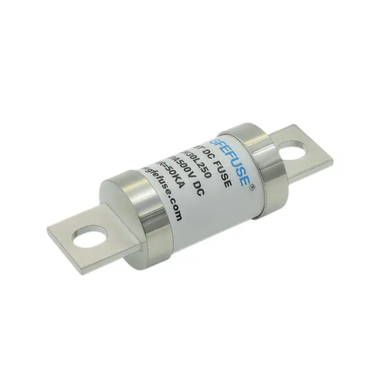
Common structural forms for BESS scenarios include stud‑mount and bolt‑on, square‑body high‑speed fuses, which can adapt to high‑current busbar assembly requirements inside battery cabinets.
Check contact temperature‑rise, contact resistance, insulation resistance and vibration resistance. Stationary ESS cabinets may experience mechanical vibration during transportation and site operation.
For outdoor‑deployed energy‑storage stations, humidity‑resistant and corrosion‑resistant construction shall be considered.
4. Relevant International Standards for Energy‑Storage Fusing
IEC 60269‑7: Low‑voltage fuses‑part 7: Fuse‑links for stationary battery energy‑storage systems. This is the core product standard for BESS‑specific DC fuse‑links.
IEC 60269‑6: Fuse‑links for photovoltaic systems (gPV type). Applicable for hybrid PV‑ESS setups.
UL 1973: Standard for stationary battery energy‑storage systems and equipment, defines system‑level safety requirements for BESS hardware.
IEC 62477‑1: Power‑electronic converter systems for general‑purpose applications, relevant for PCS inverter protection design.
Note: Compliance to standards does not automatically guarantee suitability for your exact circuit. Each project requires application‑specific evaluation by a protection engineer.
5. Typical Engineering Pitfalls in BESS Fuse Design
Using AC‑rated fuses for high‑voltage DC battery loops, relying solely on AC voltage‑rating numbers.
Selecting breaking‑capacity without checking the real‑circuit L/R time‑constant, directly using datasheet test‑condition parameters.
Ignoring thermal derating for high‑temperature sealed battery cabinets, leading to unwanted nuisance blowing.
Overlooking current imbalance in multi‑parallel battery‑strings.
Skipping TCC coordination verification; resulting in loss of selectivity and wider‑range system shutdown upon local fault.
Confusing aR semiconductor‑protection fuses with general‑purpose battery‑string fuse‑link categories.
निष्कर्ष
DC high‑speed fuse selection for stationary energy‑storage systems is not a simple voltage‑and‑current matching exercise. System open‑circuit voltage, prospective fault current, L/R time‑constant, I²t compatibility with semiconductors, thermal derating, TCC selective coordination and compliance to IEC/UL standards all together determine long‑term safety and availability of BESS installations.
System integrators and protection engineers shall evaluate each application case individually. When designing battery‑string and PCS inverter protection, refer to component datasheets, official standards and consult fuse‑manufacturer application‑engineering support.
अक्सर पूछे जाने वाले प्रश्न
Q1: Can AC‑rated fuses be used inside BESS battery DC circuits?
A: Generally no. AC fuses leverage natural AC current zero‑crossing for arc extinction. DC battery circuits lack this zero‑crossing mechanism. The breaking‑capacity of AC fuses is tested for AC conditions only and cannot be trusted for DC fault interruption, even if the AC voltage rating is numerically high. For BESS battery loops, use DC‑rated fuse‑links complying with IEC 60269‑7.
Q2: What is the meaning of L/R time‑constant for DC fuse application?
A: L/R time‑constant describes how fast DC fault current rises in an inductive‑resistive circuit. Higher L/R values create more demanding arc‑extinction conditions for fuses. Datasheet breaking‑capacity values are valid only for the published test L/R condition; real‑world circuits with larger L/R will degrade interrupting performance.
Q3: What is the difference between aR‑class fuses and IEC 60269‑7 BESS fuses?
A: aR‑class fuses are ultra‑fast‑acting for semiconductor (IGBT/MOSFET) protection inside PCS inverters and DC‑link circuits. IEC 60269‑7 fuse‑links are designed specifically for battery‑string and combiner‑box protection in stationary energy‑storage systems. They serve different protection locations and cannot be arbitrarily interchanged.
Q4: Why is TCC selective coordination important in BESS?
A: Selective coordination ensures only the protective device closest to the fault opens, while the rest battery‑system keeps working. Without proper TCC coordination, a local short‑circuit fault may trigger upstream fuses and shut‑down multiple healthy battery branches, lowering whole‑plant availability.
Q5: What standard should I follow for stationary battery‑energy‑storage fuse‑links?
A: The primary product standard for stationary‑ESS fuse‑links is IEC 60269‑7. System‑level safety requirements are defined in UL 1973 for North‑American deployments. For hybrid PV‑ESS plants, IEC 60269‑6 (gPV photovoltaic‑fuse standard) may also apply.